To focus images, the majority of telescopes encountered in optical astronomy use convex lenses that work through refraction, or concave mirrors that reflect light. Contrary to popular belief, the main purpose of a telescope is NOT to magnify objects, but to collect a larger amount of light by using lenses/mirrors that have a much larger area than the human eye.
Besides its physical size, the focal length defines the critical property of a lens or mirror. We will discuss the importance of the focal length a bit later, but first let us look at the mathematical definition that directly affects how these lenses/mirrors are made. The focal length turns out to be:
$$f=\pm\frac{1}{n-1}\times\frac{r}{2}, \:\:\:\left(1\right)$$
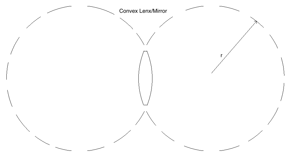
where "n" is the index of refraction of the lens glass, f is the focal length and r is the radius of curvature of the lens, which is positive in the case of a convex lens (negative in the case of concave mirrors, which we will not cover in detail). This radius of curvature can be seen clearly below for a biconvex lens geometry (the "bi" denotes the lenses are double sided with the same curvature).
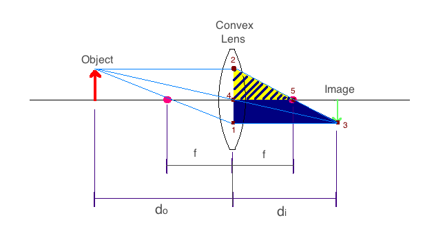
Now we define the common nomenclature used in geometrical optics. For the convex lens seen in the image below, we see the parameters do, di, and f . All of these are lengths measured with respect to the lens/mirror, where do is the "object distance", di is the "image distance", and f is the focal length. The diagram below is known as a ray diagram, where the object is the physical item we wish to focus using a lens/mirror, and the image is the place where the light would yield a crisp replica of the actual object. A solid line runs through the center of lens/mirror and is the optical axis along which the focal points lie. Note that the image appears inverted about the optical axis. Also note that this particular ray diagram is only true while the object remains farther from the lens than the focal point.
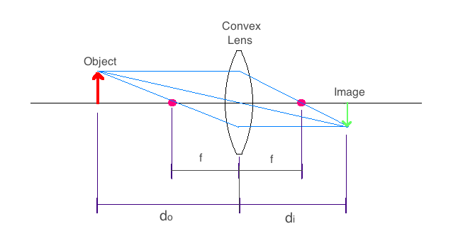
Since we are now looking at ray diagrams, let us talk about the rules of how the rays work. We choose to show all rays leaving the head of the object (arrow seen in red above), although any other position on the object would work just as well.
1. Rays that leave the object parallel to the optical axis will pass through the focal point on the image side of the lens.
2. The ray that passes through the optical axis in the center of the lens, continues undeviated by the lens.
3. A ray that passes from the object thought the focal point on the object side of the lens, will be parallel to the optical axis as it leaves the lens to form an image.
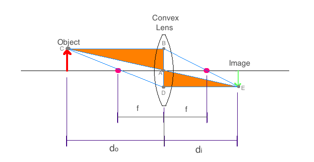
Using our convex lens diagram, we can construct a simple mathematical relationship between do, di, and f by looking at various similar triangles we can see in the diagram below.
We can see that the triangles Δ{ABC} (this denotes the triangle that has vertices at points A, B, and C) and Δ{ADE} must be similar because they are both right triangles, and the angle at point C in Δ{ABC}, is the same as the angle at point E in Δ{ADE} since the lines |BC| (which denotes the line that runs from vertex B to vertex C) and |DE| are parallel. The line |AB| is equivalent to the object height, and the line |AD| is equivalent to the image height. Since we know that the triangles are similar, the ratios of corresponding sides must be equal. So we get,
$$\frac{AB}{AD}=\frac{BC}{DE}\equiv\frac{h_o}{h_i}=\frac{d_o}{d_i},\:\:\:\left(2a\right)$$
where ho is the object height and hi is the image height. Similarly we can manipulate equation (2a) by defining the magnification of the lens as:
$$\rm{magnification}\equiv\frac{h_i}{h_o}=\frac{d_i}{d_o}.\:\:\:\left(2b\right)$$
Note that the magnification is not a property of the lens by itself, but is instead a function of how far the object is placed from the lens.
Now let us create another pair of similar triangles in the image below. We can see that triangles Δ{123} and Δ{425} are similar triangles since the angle at point 2 for both triangles are clearly the same, while lines |13| and |45| are again parallel. The line |42| is equivalent to the object height and the line |12| is the sum of the object height and image height. Now we get the relationship,
$$\frac{13}{45}=\frac{12}{42}\equiv\frac{d_i}{f}=\frac{h_i+h_o}{h_o},\:\:\:\left(3\right)$$
Finally we derive at the thin-lens equation to be,
$$\frac{1}{f}=\frac{1}{d_o}+\frac{1}{d_i},\:\:\:\left(4\right)$$
by combining equations (2a) and (3) (I suggest you all do this step on your own to work your algebra muscles). The term $\frac{1}{f}$ is known as the optical power and is generally given in units of diopters, which are simply inverse meters. These are the units optometrists use to prescribe corrective lenses or contacts (in addition to other key numbers, such as the distance between your pupils if you are getting eye glasses).
2014 Rutgers, The State University of New Jersey
Department of Physics & Astronomy,
136 Frelinghuysen Rd, Piscataway, NJ 08854
Like us on: ![]()