Rutgers Physics Student Response System
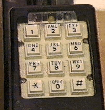
This design is hierarchical, starting with an extremely simple device at each student seat, a keypad consisting of a telephone keypad and three LED lights, red, yellow and green. These are formed into groups of at most 16, each group interfacing with a subsubstation. Each row of seats in each of the two central sections of the lecture hall constitutes such a group, served by one subsubstation. In the side sections, where it is possible to run cables from one row to another along the wall, a few rows are grouped together, making four groups in each side section. Thus we have four subsubsections for each of the two side sections, and 11 subsubstations for each of the two central sections, for a total of 30 subsubstations. Each subsubstation is mounted under one of the seats in a row which it serves.
A group of up to 8 subsubstations is served by one substation. Due to the layout of the room we are using 5 substations, although the system was designed to use 6. There is one substation for each side section of the lecture hall, one which controls the first few rows of both of the central sections, and one each for the back of the two central sections. The substations are located on the ceiling of the storage room which extends under most of the seating area of the lecture hall.
The substations have their signals brought together at a single distributor station located centrally in the storage room. It is connected to each of the substations by cables of differentially driven pairs, and is connected to the controller by a similar long cable of differential pairs.
In the lecturer's desk is the final stage, the controller, which must be connected by short ribbon cables to the interface board in the PC. This device controls the system, working through a cycle during which all keys are polled, and the state of the lights sent out to the corresponding substations. This arrangement makes it possible to transmit the data to and from the PC during an interrupt, which leaves the PC available most of the time for the higher level software which is designed to implement the instructor's needs. Each cycle lasts approximately 55 milliseconds. During this time the subsubstations go through a poll of the 48 columns (three columns each for sixteen keypads), reading the status of the four buttons in each column, and also lighting (or not) the LED light for that column. During each of these 48 steps the collecting station will gather the information from each substation and subsubstation, and reset the light controls. This is all done without help from the PC. At the end of this polling, the PC takes over control of the collecting station, quickly reading the status of all the keys and setting the state of all the lights for the next cycle. When it is done, the next cycle commenses.
More detail on the student station is available.
The function of the subsubstation is basically to compactify the signals. Six signals control which of the 48 columns is currently active. The Light enable signal is amplified, and the row input signals are buffered. This is connected to the substations by a 15 wire cable.
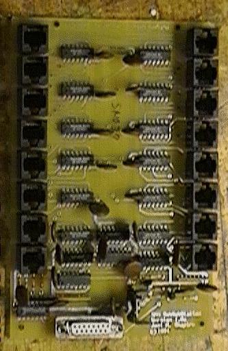
More detail on the subsubstation is available.
The subsubstation is mounted under one seat in each row (one in every other row in the side sections), and distributes the signals to, and collects those from, the individual student keypads. Each keypad is connected by an 8 conductor cable to the subsubstation. Even though five of the 8 signals are in common for all the keypads, it was deemed easier to connect, with modular cables and RJ45 connectors, if they were seperately brought to the subsubstation.
Each of the substations controls up to eight subsubstations. It is mainly a signal compactification device, together with line drivers so that the communication with the collecting station is impervious to noise. It also stores the light signals for the current cycle. The row inputs from the eight subsubstations enter multiplexers which are controlled by the SS lines generated by the controller.
More detail on the substation is available.
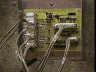
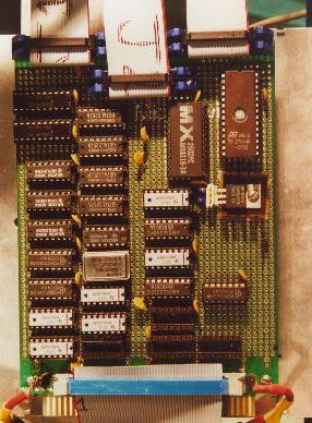
Due to the large number of signal lines (23 differential pairs to each substation and 23 differential pairs to the collecting interface), it was necessary to implement the collecting station on three boards, employing a mix of printed circuitry and wire-wrap.
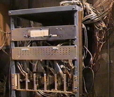
More detail on the signal distributor is available.
More detail on the controller is available. In addition, there is a description of the commercial I/O board inside the PC which communicates with the controller.