Rutgers Physics Student Response System
There is one difficulty that needs to be avoided. If a troublemaker holds down all the buttons in one column, whenever the button-press of another student is about to be sensed, not only will the corresponding row be grounded, but also the troublesome column, and therefore all the rows, so that any single button press would register incorrectly as all the buttons in one column being pressed. To avoid this problem the common row lines pass through diodes on each keypad. Thus the grounded row is unable to pull down the troublesome column, and the other rows are therefore unaffected.
Each subsubstation also controls one light-enable line, which is driven high when the light in the currently grounded column is to be lit, and not otherwise. Thus each of the LED's is lit at most 1/48 of the time, but this is sufficient to make a clear signal that the light is lit. (The polling process cycles 18 times a second, so the blinking is fast.)
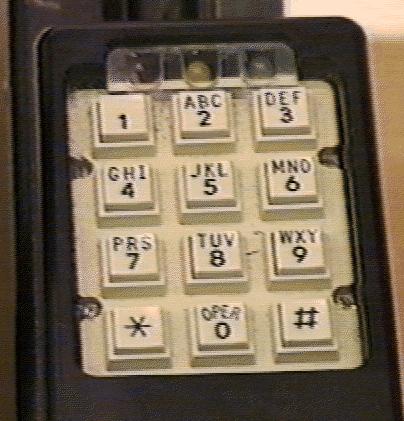
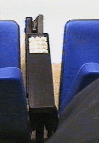
The keypad, four diodes, three LEDs and an RJ45 socket are connected to a printed circuit board I designed, and this combination is mounted in a solid black plastic armrest designed to hold it. We discovered that the exposed LEDs were subject to being wiggled back and forth until they broke off, so we added a small transparent plastic cover over the LEDs. Both the armrests and the covers were produced on a computer-controlled milling machine in the Department's mechanical shop.
Available: